
The Dreaded FCC: (Thanks to Ramsey Electronics for this excerpt from their great web site)
UNDERSTANDING PART 15 "FIELD STRENGTH" : NOT MUCH TO UNDERSTAND...
The new FCC Part 15 Rules specify a maximum "Field Strength" of your transmitted signal. Since it is unlikely that you have the equipment to carry out accurate field strength measurements in microvolts, it is useful to understand at least the theory of field strength so that you can understand both what you can expect from such transmitters, and what limits the FCC intends. Previous limits on nonlicensed FM-broadcast band devices were defined as a maximum field strength of 40µV per meter measured at a distance of 15 meters. The June 1989 revised rule specifies a maximum of 250 µV per meter, but measured at 3 meters from your antenna. The term, "250µV per meter" means that an accurate field-strength meter with a calibrated and scaled 1-meter antenna may indicate a maximum signal field strength of 250µV (In contrast, non-licensed operation from 26.96 to 27.28 MHz, your standard CB walkie-talkie, is limited to a field strength of 10,000 µV per meter at 3 meters). In all cases, the field strength of a signal decreases in direct proportion to the distance away from the antenna. Power decreases by the square of distance: for every doubling in distance, the signal power is quartered, but the field strength voltage is only halved. Using this theory, we can construct a simple chart to show the maximum permitted performance of a non-licensed FM band transmitter. The theoretical figures assume a simple 1 meter receiving antenna in all cases and do not take into consideration that reception can be greatly enhanced with larger, multi-element antennas and preamplifiers on the receiver. In the following chart, the field strength (theoretical minimum) gets stronger as you move from the edge of these circular boundaries toward the antenna:
This "exercise in meters and micro-volts" demonstrates that the FCC clearly intends to limit the theoretical range of non-licensed devices operating in this band. It also shows the potential for causing interference at a home down the street from you. But it also shows that you can legally put out quite a good signal over wider areas than you might have imagined.
For other kinds of radio services, the FCC restricts such factors as transmitter power or antenna height, which cannot really limit the possible "range" of a transmission under good conditions. By restricting the maximum field strength at a specific distance from your antenna, the FCC clearly plans for your signal to "die out" at a specific distance from your antenna, no matter what kind of transmitter power or antenna you are using. On the other hand, the FCC standards do make it legal and possible for you to broadcast on a school campus, campground or local neighborhood, as long as you remain within the field strength limitations and do not cause interference to broadcast reception.
"Why talk about acres"?
There are three reasons to translate our look at "field strength" into "acres".
The first one is easy: the numbers would get too cumbersome if we discussed your possible signal coverage in terms of square feet or square meters.
It's can be seen that your signal can easily and legally serve a school campus or wilderness camp.
And, if we remember that typical urban single-family home sites run from 1/4 to 1/2 acre on the average, it should become extremely clear that your obligation to avoid interfering with broadcast reception can eas ily involve hundreds of homes, before adding apartments!
In fact, the most significant distance in the above chart is the 1.9 µV signal strength permissible at 1260 feet (about 1/4 mile), covering a circular area of about 114 acres. A quick glance at stereo FM receiver specifications shows typical sensitivity of 1.7 µV before considering high-gain antennas or preamplifiers. Your non-licensed signal can provide serious competition to a public broadcast station fifty miles away, a station which someone in your neighborhood may have set up a special antenna to enjoy, this is why you must carefully check to see if the frequency is occupied. Calibrated "field strength meters" such as described in the ARRL Radio Amateur's Handbook can detect signals down to about 100 microvolts. To measure RF field strength below such a level, professional or laboratory equipment and sensitive receivers are required. A "sensitive" receiver responds to a signal of 1 or even .5 microvolts "delivered" to the receiver input by antenna. If the antenna is not good, the receiver cannot respond to the presence of fractions of a microvolt of RF energy.
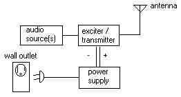
Basic Transmitter Block Diagram:
EQUIPMENT SOURCES (click on a company name to go there!)
Broadcast-Warehouse
They have a full line of very high quality amplifiers, exciters, limiters and other gear you need to get started.
LD BrewerCompany
Mr. Brewer's company has a complete line of VFO and PLL exciters and amps by FRB and Veronica and others.
PCS Electronics
Marko's company has a complete line of PC Based PLL exciters and amps. Great products and terrific support!
Progressive Concepts
features many different mfrs. gear and some of thier own, great catalog of goodies!
Ramsey Electronics
The absolute BEST construction kits! Heathkit quality in the 2000s! Very instructive for all you beginners out there! John's neat FM-100 powers Grizzly Radio.
Panaxis Inc.
Huge variety of items from thier on-line catalog, a cornucopia of goodies for radio pirates and techies
Veronica
Wide range of goodies, exciters, power amps etc. Veronica's New 20W Amp is Grizzly Radio's ROAR! UK (Available also from LD Brewer.)
North Country Radio
Nicely designed and VERY compact is NCR's MPX-96 PLL FM exciter, an AM rig is available too!
NRG Kitz
Well designed, laid out and complete exciters, amps, quick friendly service. Schematics included!
Obtain a set of small hand tools:
Diagonal Side-cutters, Wire Strippers, Needle-nosed Pliers, 15-25W Soldering Iron, Aluminum Clip-on Heat Sink
and practice, practice, practice your soldering skills! You MUST have GOOD soldering skills, period. Be sure your iron (NO GUN!) has a SMALL 1/8"-1/16th in. tip. Weller, Ungar make excellent soldering tools, though, in a pinch, the 15-25 watt knock-offs from Radio Shack will certainly do the job. Use 60/40 ROSIN core, Tin/Lead (small diameter -.032 or so) solder ONLY! Use the small aluminum clip-on heat-sink to protect those !##$!$ diodes and transistors and/or chips that there will be plenty of. You'll need practice with diagonal side cutters (dikes) and the small pair of needle nosed pliers too. The wire strippers should be useful for 14 - 28 gage wire. BEFORE YOU START ON YOUR KIT - Practice your soldering skills FIRST! Practice until you get it right! Radio Shack has small printed circuit boards, buy one and stuff it full with resistors available from the same source, then practice soldering 'til you get it right. This will keep you from cooking the living heck outa' those @#$$#! diodes and transistors, 'cause, believe me, they CAN'T take the heat! Overheating = meltdown internally and POOF! all your hard work is up in smoke! Keep that soldering tip clean too…use a small sponge, dampened with plain water, to wipe the tip before soldering anything! The following site has all you need to know about soldering, check it out:
Soldering How-To Site
--------------------------------------------------------------------------------
FM EXCITERS / EXCITER-AMPLIFIERS
This is the "heart" of your station, the creator of the oscillations that will be heard as your "station". It has an oscillator, an audio input section, a FM modulation section, a RF pre-amplification stage and an RF amplified output stage and sometimes an RF filter stage. Generally they are constructed on a single small printed circuit board. They are of two broad types, VFO and PLL. VFO (Variable Frequency Oscillator) units are generally cheaper per watt, and can drift off frequency somewhat more easily than PLL (Phase Locked Loop) types. Drifting can be minimized if good building and operating practices are used. Keep all wire leads short, keep VFO units powered on, and mount them in an enclosed metal box, properly cooled and grounded. PLL exciters stay on frequency better than VFO types and (generally) are somewhat more expensive. The manufacturers/suppliers on this page all have exciters for sale. You need ONE either sufficient to cover the entended audience OR with sufficient output to DRIVE and RF amplifier. Looking for some scratch build ideas? Try the following sites.
Click on the word..."SCHEMATICS".
Schematics!...MORE SCHEMATICS!
--------------------------------------------------------------------------------
Which should you buy?
You need only one exciter, which one? There are many listed at Broadcast-Warehouse, PCS Electronics,’, LDBrewer's, NRG Kitz, Veronica's and Progressive's and all the other mfr's sites. I'll take a few of them (in no particular order) and try to describe each as best I can. Remember these are my opinions, and others may feel differently; nonetheless I’ve ACTUALLY built and/or operated each of the following in my own "test bed" and the comments given are my experience (AND my students!) with each one. These units are to be regarded as only a FEW of what is available or what you could scratch build for yourself. Here goes…
Broadcast-Warehouse PLL 1 Watt Stereo Exciter. Built, ready to go. High quality parts, easy to tune, dip-switch tuning. Needs an external supply. Similar in layout to the Panaxis exciter, quite compact. For those with a fear of soldering, and with .8-1.3 Watts out, this little guy might be all you need to get started. Less than 100.00US, from the UK.
NRG Kitz, Mono PLL PRO II 1 Watt Exciter, Built, High quality parts, dip switch freq. selection. External 12vdc supply required. Large board (5.5" X 6.5"). Has built in low-pass filter, a plus! It IS Mono, if you want Stereo a Stereo Coder is available as well.
The RAMSEY FM-10, A BASIC transmitter that is suitable for around the house ie: "Yardcaster" and the important function of LEARNING…it works, it's cheap ($34.00) and does a credible job for a small expenditure. If you want to use your setup for around the house, yard and surrounding few acres this may be all the transmitter you really need. Follow Ramsey's instructions implicitly and you'll have no problem getting it up and on-the-air in one afternoon. It has a built in antenna, stereo inputs and is dead easy to build. Many of my students have built these and have been very pleased with the results. This is a fun and instructive electronics kit. It is legal too if built and operated as Ramsey describes as far as the FCC is concerned.
Ramsey Electronics, FM25A, Stereo input, PLL, nice quality parts, great factory service, easiest PLL to build, instructions are GREAT with a real instructive (like Heathkit of old) approach to the chore (fun) of building. You actually learn how the FM25 works as you build it. Output = 8-25 mw. Lot's of modifications listed on the alt.radio.pirate newsgroup. Needs good external 12v power supply and a metal case. About $130.00 US. FCC is OK with it as built using Ramsey’s instructions and parts.
Ramsey Electronics, FM-100, Stereo input w/level controls, PLL, digital tuning feature, 120vac line power, has nice full metal case w/ digital freq. display included. Easy to tune from the front panel. Highly instructive approach used to assemble the unit, much like Heathkits. Output = 25 - 100mw. Can be upgraded or ordered as the "export" version…this adds an internal (socketted) 1 watt power amp module. About $250.00 US for the kit. The plug-in One Watt module is available from Ramsey w/letter re: "for export" or from LDBrewer w/o explanations.
Veronica, 1 Watt Pro PLL FM Transmitter/Driver, Mono, PLL, needs 12v ps and case. Good quality kit, basic instructions...stuff and solder, gets points for circuitry and board design and layout. 1 watt output (1000 mw), they have others, many with higher and lower output, this is an excellent buy. UK designed. About $130.00 US Veronica has many others from 1 Watt VFO to 5 Watt PLL. Not "legal" per the FCC. Available from LDBrewer, or Veronica in the UK.
Click Here to go to the Veronica Review Site:
http://www.irational.org/sic/radio/veronica-1w.html
Panaxis FMX, Mono, PLL, needs power supply and case. It's a nice quality kit, somewhat more difficult to build than the others above as the building instructions are just that, with little mention of how individual parts affect the whole. Excellent circuit design and variable power output, 25-250mw. $130 US
Free Radio Berkeley PLL Xmitter, Mono, needs case and power supply. Basic Parts Kit. More difficult to build than the first two with difficult to decipher instructions. No schematic, Grrrrrr. 100-150mw output. $125.00 US FRB products are best bought from LD Brewer as FRB can be a s-l-o-w shipper.
PCS Electronics PLL Xmitter, Mono, needs PC for power. Nice board, well designed, Easy to install. No more difficult to start up than openning a PC's case inserting the board in an available slot, powering up and following the simple but logical instructions. Up to 1W output. $125.00 US PCS is a very reliable shipper with super support if needed.
North Country Radio MPX-96, PLL, needs case and power supply. Easy to assemble, the board is small and quite crowded with components. Easy to tune w/ variable power out of 25-500mw. Find a copy of June 1997's Electronics Now, the MPX-96 is a CONSTRUCTION ARTICLE! Complete with board layout, schematic et al. A great buy at $75.00 US.
--------------------------------------------------------------------------------
POWER SUPPLIES
With MOST units (excepting the internal PC board exciters) You will need a good 12v , 2 ampere (minimum) to 10 ampere (maximum), regulated and filtered DC power supply. Please no "wall - wart" supplies need apply. I'm not fond of switching type power supplies either, though there ARE good ones available. Get a well filtered "linear" type design. Expect to pay $35.00 - $125.00 US. My favorite is to skip the power supply altogether and use a 12v lead/acid car battery and charger. Simply recharge the battery after you are off the air. DO NOT leave your charger connected while you are on-the-air as this is HUM city! Figure Ampere Rating needed like this:
P (Power in Watts) / (divided by) Volts) X (times) 2 = (I( Current in Amperes) AS:
10W / 12V = .83 A X 2 = 1.66 A (at 12 volts) / .50 (50% efficiency) = 3.32 Amperes
Depending on the efficiency of your circuit this 3.32 Amp supply would be the MINIMUM amperage required.
--------------------------------------------------------------------------------
ANTENNAS
An properly tuned (low VSWR) antenna, J-pole, 5/8ths wave vertical, 1/4 wave dipole, broadband etc. as high up as you can get it makes up for LOTS of power and is money and time WELL spent! Remember that signal propagation at FM frequencies is virtually line-of-sight. City miles are longer than country miles, forest miles are farther than desert miles. You can build an inexpensive 1/4 wave antenna from 1ea.- SO-239 Chassis mount RF connector (Radio Shack) and 5 ea. bronze welding rods (welding shop), cut to the proper length. The formula you can use to determine element size (1/4 wave) is:
1/4 Wavelength in Inches = (234 / Freq. in MHz) X 12
Here's an example:
234/90.1 MHz = 2.5971 feet
2.5971 feet X 12 = 31.165 inches.
here's a picture to help you do the construction
See other antennas at the following sites:
The dipole and decibels defined: decibels related to dipole antenna - a whatis definition
Half - wave dipole site: http://home.iae.nl/users/bergervo/gouy/dipole.html
The J Pole Described: http://www.vk1.wia.ampr.org/bulletins/jpole.html
More Antenna Facts: PACKET RADIO OPERATOR'S COMPLETE GUIDE TO BUILDING AMATEUR RADIO J-POLE ANTENNAS and Jpoles !!!
You'll pay as little as $5.00 to build the lil' 1/4 wave job, up to $150 or more. I like and use the 5/8ths wave Comet antenna, it's low vswr (good 50 Ohm match) as well as terrific quality of construction, its about $110.00 US. See the Progressive site for details of the Comet antenna series. Ramsey Electronics now has a 5/8ths wave vertical that deserves a look see! Here's the sheet that comes with the COMET 5/8ths, it has the tuning info too!
--------------------------------------------------------------------------------
COAXIAL CABLE ie: coax
Coax is NOT coax, sorry but the quality of this stuff never ceases to amaze me, there is real JUNK out there waiting for your time and energy to install. Buy BELDEN, it works, it's GOOD, it's impedance characteristics are KNOWN and are impeccable. The common RG-58 from Radio Shack is NOT BELDEN CABLE, and you could do a lot better than settle on that stuff though a short run of 15 feet or so is certainly ok, just stay away from 100 ft runs of the stuff. Lousy (lossy) coax will attenuate (that means DROP) your signal significantly and the cause will NEVER show up except at the listener's receiver! BELDEN makes various coaxial cable products, some ideal for our purposes that have low loss (loss is measured in decibels, dBs, at our frequencies. Remember that 3dB's represents 1/2 of your signal either LOST or GAINED. It goes like this:
RG-8 and RG-58 are 50 Ohm impedance cable.
RG-6 and RG-59 are 75 Ohm impedance cable.
Most equipment is matched for 50 Ohm cable and 50 Ohm antenna impedance. Check with your manufacturers BEFORE you buy and start hacking your expensive coax! You need enough to reach your antenna from your transmitter PLUS a few extra feet for use as jumpers from your excitter to the amplifier, vswr meter etc. Don't buy more than you need! Extra lengths of ANY coax HURTS in losses thru' connectors and that pesky VSWR ratio suffers too. Click on the Belden Link to inspect their RG-8U Coax specifications for yourself. Nice stuff...it's what I use for Grizzly Radio's inter-connects and output coax.
DURHAM RADIO'S Coax Info Page For: 8214 50 Ohm Transmission Cable
Check the following site for your coax (BELDEN) needs:
Durham Radio
--------------------------------------------------------------------------------
AMPLIFIERS
Amplifiers are pretty boring pieces of equipment. They amplify your measly little exciter's signals to levels that will deliver solid reception to your listening audience. More watts cost more money, period. Most amplifiers are simple one or two transistor class C amplifiers, they conduct (draw current) only when there is an input RF signal. Some are made of the newer technology modules, handy as heck in designing and building your own, but not essential. They MAY also have filtering stages built into the design. One watt output in the FM Band (88-108MHz) will get you line of sight transmission (radius) of approx 1 - 1.5 miles. This depends on the antenna used and it's height, the higher the BETTER! 5 watts will double your effective range. 10 watts...possibly 4 - 5 miles. Greater wattage out will deliver a quality signal further depending upon the terrain. Remember that city miles are longer than country miles etc. Start small...it's easier! The FRB series of amplifiers are all easy to build and do as they say. Use a FAN on all but the lil' 6 watter. Contact LD Brewer for his specific recommendations re: Veronica Amplifiers. Remember it takes 10 Times the power out (ERP...Effective Radiated Power) to create twice the signal strength at the receiver! Expect to pay $30 - $200 for your power amp. Cheap Hint Follows: Ramsey Electronics makes a 2 meter 40 watt amplifier for less than $50.00 that can EASILY be mod'd (replacing a few cheap parts) to work in our 3 meter band.
--------------------------------------------------------------------------------
FILTERS
These devices are used to decrease the output of frequencies with which you are NOT broadcasting. These OTHER frequencies are known as harmonics and you don't want any! Harmonics are your enemy! Filters offer cheap protection for your precious signal. FRB makes neat little kit 7 and 9 pole Butterworth filters that will do in a pinch and which are less than $20 US. You can spend lots on commercial units ($25.00 - $150.00 US). I'm cheap so I use an FRB 9 pole filter mounted in it's own aluminum box with in/out SO-239 chassis connectors. See Progressive's site for some nicely designed and built filter units.
--------------------------------------------------------------------------------
SWR METERS
You get what you pay for when you buy a VSWR meter. Cheap ones are worthless, they'll lie and make you confident when you should be otherwise. Bird makes the BEST and they are expensive at $300+ US, however, Diawa, Diamond, Standard Communications are all good, servicable units that you can trust and will last and last. Make sure you get the model designed to work in the 88-108MHz (3 meter) FM band! In a pinch you can use a CB type for RELATIVE power out and VSWR readings but it will be lying to you about everything you're reading. The Radio Shack CB SWR meter is about $30.00. Expect to pay $75.00 - $150.00 US for a good one. VSWR should read as close to 1:1 (1:1 is PERFECT) as possible but don't expect better than 1.5:1 in typical setups which is really quite good indeed.
--------------------------------------------------------------------------------
DUMMY LOADS
You'll have a perfect VSWR reading every time with a dummy load! No signal out but what the hey! Easy to build a little one, pre-built ones can cost $30 - $100 or so depending on the wattage it must handle. To build one suitable for up to a 1 watt exciter...4 ea. 220 Ohm 1/2 watt CARBON COMPOSITION resistors, DO NOT USE WIRE-WOUND OR METAL FILM type resistors! A S0-239 connector will work as a body, solder one end of each resistor to a crimp on wire lug and screw it to the outer shell of the connector. Twist the other ends together and stuff 'em into the center conductor and solder. Dip the works in shellac or tool goop and there you are! You can test your exciter to your hearts content with a PERFECT VSWR! Progressive has nice DM's available.
--------------------------------------------------------------------------------
CAUTIONS!
When soldering ALWAYS use a small aluminum heat sink or alligator clip on the leads of those transistors and diodes, you'll fry 'em if you don't and that'll be the end of it!
I take special precautions when soldering chips. First, use a chip socket if you can, if you can't, then solder carefully with the least heat you can muster, 15w is plenty! Then "Scatter Solder" as follows: Solder pin 1 first, then move to the other side of the chip and solder pin 8, come back and solder pin 2, then go back and solder pin 7, etc. etc. This will keep the average temperature down on your chip and help assure it will function properly after you are done.
When you are putting up that antenna watch out for overhead power wires for gods sake, I don't know how many times I've read of some poor fool crossing those damned wires and killing himself by electrocution or the resulting fall. WATCH OUT! BE CAREFUL! A good pirate is a live pirate!
Double check that supposed "clear" frequency at the limits of your range. You don't want to be walking on other legal operators (or pirates either!), so check at all points of the compass BEFORE you commit all the time and energy you're about to on an interfering signal. REMEMBER this:
Radio Horizon = 2 X (SQR Height)
An example: 2 X (SQR 36 feet)
2 X 6 = 12 (miles)
Yes, a signal, YOUR signal, WILL reach to that horizon, whether anyone hears it depends on the relative goodness of the listener's receiver, the bumpiness of the terrain and your ERP (Effective Radiated Power).
Try this link to help you find that "clear" frequency:
Radio Station Locator Page: http://207.91.54.150/radiostation
Another helpful station finder: http://wmbr.mit.edu/stations/locate.html
Find it here too: http://www.metronet.com/~chipk/main.html
--------------------------------------------------------------------------------
Resistor Color Code
--------------------------------------------------------------------------------
Common Electronic Schematic Symbols
--------------------------------------------------------------------------------
This is an easy way to mount your exciter/amp in a decent metal case...
--------------------------------------------------------------------------------
Grounding (It matters!)
Better is better, and that means GROUNDING RODS. What are they? Generally you'll find them at hardware stores or Home Depot in the plumbing area or electrical area. They are usually mild steel plated with copper, 10 feet long bu 1/2 - 5/8ths of an inch in diameter.You drive them (buy 2) into the ground in the wettest soil area nearest your receiver OR transmitter until only a 4-6" part remains above ground level. Then you fasten a 12gage or larger solid copper wire and string this via the shortest possible route to your equipment. I then use a common bus bar scheme to ground all equipment to this wire. In certain areas of the country you might need to drive in several rods (more than 2) to achieve sufficient grounding. Cosult the map below for your soil's conductivity, let it be a guide to how much grounding you need in your location.
--------------------------------------------------------------------------------
OTHER PIRATE RADIO SITES
LPFM FAQ: http://www.irational.org/sic/radio/faqa.html
FM10 - BA1404 MOD'S:Da' FM-10 Doxs
PEG-LEG PIG'S PIRATE RADIO PAGE: http://members.tripod.com/~amn92/index_main.htm
SCHEMATICS AND KIT INFO: http://members.tripod.com/~transmitters
LPAM Your Thing? Try the Medium Wave Alliance:MWA Lobby
Get Paid to Write Your Opinions! http://hnlute.epinions.com
After you read all of this feel free to email me for explanations or help... hnlute@gmail.com

Last
Update 11/11/2009